CS 201: Computer Architecture
Computer Architecture I.
Summary:
- The organization of a simple RAM (Random Access Memory) as 2A memory registers of B bits each, with an A-bit MAR (Memory Address Register) and a B-bit MDR (Memory Data Register),
- How memory reads and writes work.
- Alternate views of the organization of a simple Von Neumann computer in terms of main memory (RAM), CPU (Central Processing Unit) consisting of central registers, the ALU (Arithmetic Logical Unit) and the CU (Control Unit).
- The fetch-decode-execute cycle.
- Start of the specification of the TC-201 computer.
Perlis epigram #44: Sometimes I think the only universal in the computing field is the fetch-execute cycle.
The term "random access memory" conveys that the time to access any particular value in the memory is (essentially) the same, as opposed to a "sequential access memory" like disk or magnetic tape, where accessing "the next" value can be considerably less time-consuming than accessing an arbitrary value (because of the travel time of the physical media, eg, radial movement of a disk head, the spinning of the disk, or the winding of the tape.)
We abstract the interface for a random access memory (RAM) as follows. There are two special registers, the memory address register (MAR) and the memory data register (MDR), and a signal indicating whether to read from the memory or write to the memory. The memory itself consists of a number n = 2A of memory registers, each of which holds B bits. Then the MDR is also B bits (it can hold the value of one memory register) and the MAR is A bits (it can hold the address -- a number between 0 and 2A-1 -- of any one of the memory registers.) When the operation is a read, the contents of the memory register addressed by the MAR is copied to the MDR. When the operation is a write, the contents of the MDR is copied to the memory register addressed by the MAR, replacing its previous contents. (In the "tiny RAM" example of the previous lecture, there was no MDR, and we had A = 2 address bits, n = 2A = 4 memory registers, and B = 4 bits in each memory register.)
To use this interface to read the contents of a register from RAM, we put the address of the register in the MAR and send the "read" signal. This causes the contents of the addressed memory register to be copied to the MDR, where we may access it. To place a particular value in a particular memory register of the RAM, we put the address of the register in the MAR, and put the value we wish to store in the MDR and send the "write" signal. This causes the contents of the MDR to be copied into the addressed memory register. (The previous contents of that memory register are replaced by the new contents.) These operations are at the "micro-instruction" level, not visible to a person programming the computer at the assembly language level.
(There was an aside on how "core memory" works, and an example of 1024 bits of it from the Computer Museum in Boston. The 4 Gigabytes of RAM on a modern laptop were calculated to be equivalent to more than 32 million such arrays of tiny ferrite cores.)
We looked at two "block diagrams" of the organization of a Von Neumann computer.
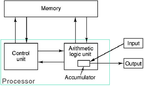
Both of them showed main memory, the arithmetic/logical unit (ALU), the control unit (CU), and input/output functions. The ALU and CU are usually grouped together into the "central processing unit" or CPU. The main memory is the RAM that we discussed above. Input/output covers communication of the central computer with devices such as keyboards, mice, displays, microphones, speakers, DVD players, network interfaces, and secondary storage like disks, and so on. The ALU can be thought of as a collection of combinational circuits to perform operations on data like addition, subtraction, comparison, logical operations, and the like. The CU is a collection of registers and combinational logic that collectively are responsible for fetching and executing instructions, (in some sense the conductor of the orchestra that is the computer.) Both diagrams indicated one or more "central registers", that is, registers local to the CPU that are integral to the execution of programs by the computer.
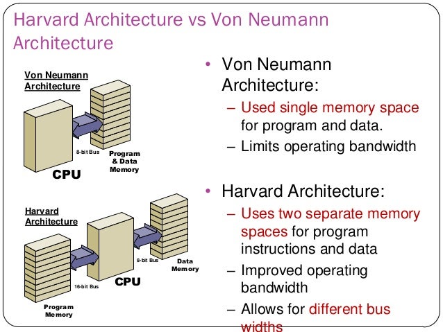
The "Von Neumann architecture", in which the instructions of a program and the data for the program are both located in the same (main) memory, is generally contrasted with the "Harvard architecture", in which there are separate memories for the instructions of a program and its data.
In the Von Neumann architecture, a program is run as follows. There is a CPU register called the "instruction counter" or "program counter", which holds the address of the next instruction to execute. The instruction is "fetched" (read from main memory into a CPU register called the "instruction register") and "decoded" (which determines what operation is specified by the instruction) and "executed." The execution of one instruction may involve:
- copying data between central registers,
- copying data from central registers to memory (using the RAM write capability),
- copying data from memory to central registers (using the RAM read capability),
- sending data to output devices,
- receiving data from input devices, or
- routing data to ALU circuits to perform operations
- and routing the results to central registers or memory registers.
Usually after an instruction is executed, the program counter is increased by 1, and the whole "fetch-execute" cycle is repeated to execute the next instruction in memory. This process continues until a halt instruction is executed. Some instructions (eg, jumps and skips) cause a different update to the program counter, altering the pattern of executing consecutive instructions.
We describe the design of the TC-201 computer ("TC" for "tiny computer" or "toy computer"), to make the ideas of computer architecture, machine language and assembly language concrete. It consists of 3 parts: main memory (or RAM), a central processing unit (or CPU), and an input/output system to communicate with the outside world (that is, you, the user.)
The main memory, or RAM, of the TC-201 consists of 4096 memory registers, also called "words", of 16 bits each, addressed by integers from 0 to 4095. Because 4096 = 212, 12 bits are sufficient to represent any memory address. There is a central register: the accumulator (or ACC), which has 16 bits. The other CPU state consists of the program counter (or PC), which has 12 bits and holds the address of the next instruction to be executed, the run-flag, which is one bit and indicates whether the computer is running (1) or halted (0), and the arithmetic error bit (or AEB), which indicates whether there has been an arithmetic overflow error.
TC-201 instructions.
Each TC-201 instruction occupies 16 bits in the RAM. The bits are numbered 0 to 15 from left to right. The top four bits, 0 through 3, are the operation code (or "opcode") and determine which operation will be executed. Thus, there could be 24 = 16 possible different opcodes. Most of the instructions involve the contents of the accumulator, and some of them also involve the contents of a word in memory. In that case, the remaining 12 bits, 4 through 15, are the address of the memory register that will be involved in the operation.The TC-201 instructions mentioned in this lecture:
  opcode  operation
  ------  ---------
  0000    halt -- stops execution (sets the run flag to 0)
  0001    load -- copies contents of addressed memory register to accumulator
  0010    store -- copies contents of accumulator to addressed memory register
If we denote the contents of the accumulator by acc, the address field of the instruction by addr, and the contents of the memory register with address addr by Mem[addr], we can abbreviate the function of load as acc := Mem[addr] and the function of store as Mem[addr] := acc, where := is an assignment operator.
Computer Architecture II.
Summary:
- Computer representations of integers: unsigned binary, sign/magnitude, one's complement, two's complement.
- Choice of a representation for this term's TC-201: sign/magnitude.
- Start of task: read in a zero-terminated sequence of numbers, print them out in reverse, and then halt.
In the TC-201 we have 16 bits to represent an integer. There are 216 = 65536 possible patterns of 16 bits, so we could represent that many different integers. If we needed only non-negative integers, a natural choice would be "unsigned binary", which would just be the 16-bit binary representations of the numbers 0 through 65,535 as the patterns 0000000000000000 through 1111111111111111, respectively.
However, we'd like to represent a range of positive and negative integers, but the number of integers from -n to n is 2n+1, an odd number. As a result, the number representations we'll consider each have an "anomaly" because the number of patterns is even. The three systems we consider are: sign/magnitude, one's complement, and two's complement. For illustration, we'll consider the systems using just 4 bits (instead of 16) -- the principles apply to any number of bits, for example, the more common 32 or 64 bits of modern computers. With 4 bits we have 24 = 16 possible bit patterns. Here is what they represent, in unsigned binary and in each of the three systems we consider.
  bit pattern   unsigned binary  sign/magnitude   one's complement   two's complement
  -----------   ---------------   --------------   ----------------   ----------------
    0000               0                 0                 0                 0
    0001               1                 1                 1                 1
    0010               2                 2                 2                 2
    0011               3                 3                 3                 3
    0100               4                 4                 4                 4
    0101               5                 5                 5                 5
    0110               6                 6                 6                 6
    0111               7                 7                 7                 7
    1000               8                -0*               -7                -8*
    1001               9                -1                -6                -7
    1010              10                -2                -5                -6
    1011              11                -3                -4                -5
    1100              12                -4                -3                -4
    1101              13                -5                -2                -3
    1110              14                -6                -1                -2
    1111              15                -7                -0*               -1
(The asterisk (*) indicates the "anomaly" in each system we consider: a second representation of 0 in sign/magnitude and one's complement, and a number, -8, with no corresponding positive number in the representation, in two's complement.) Note that all three systems represent the numbers 0 through 7 in the same way (except for the extra representations of 0) -- as 0 followed by the 3-bit unsigned binary representation of the integer; this is also the unsigned binary representation of these numbers. (In general, for b bits, the numbers 0 through 2b-1-1 are represented as 0 followed by the (b-1)-bit unsigned binary representation of the number.) The three systems differ in how they represent negative numbers.
For sign/magnitude, the representation of a negative number is 1 followed by the 3-bit unsigned binary representation of the absolute value of the number. Thus, the high-order bit is a sign bit (0 for + and 1 for -), and the remaining bits give the magnitude (or absolute value) of the number. To convert a positive to a negative number, it suffices to change the high-order bit from 0 to 1, and to convert a negative to a positive number, it suffices to change the high-order bit from 1 to 0. Note that we have two representations of 0, namely 0000 and 1000, that latter being referred to as -0.
For one's complement, the negative of a number is found by complementing each bit individually (changing 0 to 1 and 1 to 0.) Thus, we represent -1 in 4-bit one's complement by complementing each bit of 0001 to get 1110. Of course, since complementation is self-inverse (the complement of the complement is the original argument), the negative of a negative number is also found by complementing each bit. In one's complement (also) the number zero has two representations: 0000 and 1111 -- the latter being referred to as -0.
The rationale for two's complement is that it implements arithmetic modulo 2b, where b is the number of bits. If we consider the integers 0 through 15 modulo 16, then we have 1+15 = 0 (modulo 16) and 5+11 = 0 (modulo 16). Thus, modulo 16, 15 "behaves like" -1, in the sense that 1 and 15 add to 0 (modulo 16), and 11 "behaves like" -5. If we consider the 4-bit unsigned representation of 15, we have 1111, which is the representation of -1 in 4-bit two's complement arithmetic, and the unsigned 4-bit representation of 11 is 1011, which is the representation of -5 in 4-bit two's complement. The number 8 is a bit anomalous modulo 16, because 8+8 = 0 (modulo 16). The representation 1000 is taken to be -8, which means that the high-order bit signifies whether the number is negative (if the bit is 1) or non-negative (if the bit is 0.) Why would two's complement be desirable? If you recall the circuit we designed to add two 4-bit numbers to get a 5-bit sum, if we just ignore the high-order bit of the result, the circuit computes the sum of its two inputs, modulo 16. Two's complement is in fact the most common choice for the representation of integers in modern computers.
The rule some have learned for negating a two's complement number is to complement each bit individually and then add 1. For example, to complement 5, we start with 0101 and complement each bit: 1010, and then add 1: 1011, which is the correct representation of -5 in two's complement. Going the other direction, from -5, we start with 1011, complement each bit: 0100, and add 1, to get 0101. Why does this work? Hint: complementing each bit is equivalent to subtracting the unsigned value of the number from 15.
In a class vote (years ago), it was decided that the TC-201 computer would have sign/magnitude representation of integers. We also decided that skipzero will skip on both positive zero (0000 0000 0000 0000) and "negative zero" (1000 0000 0000 0000).
Next, we turn to the following task: read in a zero-terminated sequence of numbers, print them out in reverse, and then halt. A sample interaction with the user might look like the following.
    input = 17
    input = -13
    input = 22
    input = 0
    output = 22
    output = -13
    output = 17
We start with the following idea, which is NOT a solution.
    read-num:  input
               skipzero
               jump store-num
               jump produce-output
    store-num: store num
               jump read-num
    num:       data 0
The reason this doesn't work is that the first number read in
will be stored in num, and then the second number read in will
be stored in num (overwriting the first number) and then the third
number will be stored in num (overwriting the second number), and
so on.
When this jumps to the code for produce-output, only the latest
number read in will be available in num, and we won't have
the information we need to print out the reverse of the sequence
of numbers read in.
(See the next lecture for how we solve this problem.)
Computer Architecture III.
Summary:
- Reading in and storing a zero-terminated sequence of numbers,
- new TC-201 instructions loadi (load indirect) and storei (store indirect).
In the preceding lecture, we considered the problem of reading in a zero-terminated sequence of numbers, printing out the reverse of the sequence, and halting. Here we temporarily simplify the task to reading in a zero-terminated sequence of numbers, storing them in consecutive memory locations, and then halting. (The task of printing out the reverse of the sequence will be deferred to the homework.) In the last lecture, we considered the following, NOT a solution.
    read-num:  input
               skipzero
               jump store-num
               halt
    store-num: store num
               jump read-num
    num:       data 0
This is not a solution because each number read in overwrites
the previous one, so that at the end only the most recently
read number will be available.
What we need is a way of storing into num the first time
through the loop, storing into the next memory location the
next time through the loop, and so on.
We considered two possible solutions to this problem. The first, highly deprecated, solution is to write self-modifying code. That is, we may treat the store instruction as data, load it into the accumulator, add 1 to it, and store it back into its memory register. This would have the effect of changing the instruction from "store 6" (in the original program, because num corresponds to address 6) to "store 7", so that the next number read in from the user would be stored in memory location 7. The code for this kind of solution would be as follows.
    read-num:  input
               skipzero
               jump store-num
               halt
    store-num: store num
               load store-num
               add constant-one
               store store-num
               jump read-num
    constant-one: data 1
    num:       data 0
Once your TC-201 simulator is running, you might want to
try this running this program to see what it does.
Self-modifying programs are very difficult for human beings
to understand, debug, and maintain, because of the large
amount of "state" the human has to keep track of -- not only
the current data values, but also the current version of the
program that is running. (See juggling eggs)
(When computer memory was scarce, self-modifying code effectively
recycled memory addresses - like a studio apartment where you cook,
eat, work, and sleep in the same room. You had to make do with
what you had.)
So instead we introduce the last two instructions for the TC-201 computer, which allow us to implement "pointers" in our programs. [Note: we also have the following instructions: shift, and, and xor, described in hw6.rkt.] A pointer indicates where in memory an operation is to be performed. The two instructions are as follows.
    name    opcode     operation
    ----    ------     ---------
    loadi    1011      acc := Mem[extract-address(Mem[addr])]
    storei   1100      Mem[extract-address(Mem[addr])] := acc
The names stand for "load indirect" and "store indirect".
The extract-address() operation indicated above means that
we extract the rightmost 12 bits of a 16-bit quantity and treat
it as the address of a register in RAM.
Thus, the instruction "loadi addr" is executed as follows: read from memory the contents of the register with address addr, and take the rightmost 12 bits of that as another address, addr'. Copy the contents of the memory register with address addr' to the accumulator. Finally, increment the program counter, as usual. Similarly, the instruction "storei addr" is executed as follows: read from memory the contents of the register with address addr, and take the rightmost 12 bits of that as another address, addr'. Copy the contents of the accumulator to the memory register with address addr'.
The following example may help illuminate the function of loadi and storei. We will simulate the TC-201 for three instructions, starting with the following configuration.
    acc:   0000 0000 0000 0000
    pc:         0000 0000 0000
    rf:                      1
    aeb:                     0


address    contents of memory register addressed
-------    -------------------------------------
    0      1011 0000 0000 0101
    1      1100 0000 0000 0110
    2      0000 0000 0000 0000
    .
    .
    5      0000 0000 0011 0100
    6      0000 0000 0011 0111
    .
    .
    52     0000 1111 0000 1111
    53     1010 1010 1010 1010
    54     1111 0000 1111 0000
    55     0101 0101 0101 0101
Because the pc contains address 0, we read the instruction at
address 0: 1011 0000 0000 0101, decode the opcode 1011 to find
that it is a loadi instruction.
We take the address field of the instruction, 0000 0000 0101,
which is address 5, and read the contents of memory register 5,
which is 0000 0000 0011 0100.
We take the rightmost 12 bits of that, 0000 0011 0100, and interpret
it as address 52.
Then the contents of memory register 52 are copied to the accumulator,
and the program counter is incremented by 1, to produce the
following configuration after the loadi instruction completes.
    acc:   0000 1111 0000 1111
    pc:         0000 0000 0001
    rf:                      1
    aeb:                     0


address    contents of memory register addressed
-------    -------------------------------------
    0      1011 0000 0000 0101
    1      1100 0000 0000 0110
    2      0000 0000 0000 0000
    .
    .
    5      0000 0000 0011 0100
    6      0000 0000 0011 0111
    .
    .
    52     0000 1111 0000 1111
    53     1010 1010 1010 1010
    54     1111 0000 1111 0000
    55     0101 0101 0101 0101
Now the program counter holds address 1, so we read the
instruction at address 1, which is 1100 0000 0000 0110.
We decode the opcode, 1100, and find that it is a storei instruction.
We take the address field, 0000 0000 0110, which is address 6,
and read from address 6, getting the contents 0000 0000 0011 0111.
We take the rightmost 12 bits of that as an address, address 55,
and copy the contents of the accumulator to memory register 55.
The program counter is then incremented, resulting in the following
configuration after the storei instruction has been executed.
    acc:   0000 1111 0000 1111
    pc:         0000 0000 0010
    rf:                      1
    aeb:                     0


address    contents of memory register addressed
-------    -------------------------------------
    0      1011 0000 0000 0101
    1      1100 0000 0000 0110
    2      0000 0000 0000 0000
    .
    .
    5      0000 0000 0011 0100
    6      0000 0000 0011 0111
    .
    .
    52     0000 1111 0000 1111
    53     1010 1010 1010 1010
    54     1111 0000 1111 0000
    55     0000 1111 0000 1111
Note that the contents of registers 5 and 6 are unchanged,
but we have copied the contents of register 52 (pointed to by register 5)
to register 55 (pointed to by register 6).
Next, the instruction at address 2 is executed.
Because it is a halt, all that happens is that the run flag (rf)
is set to 0, and execution halts.
We can make use of the idea of a pointer (which we repeatedly increment) and the storei instruction to solve the problem of reading in a zero-terminated sequence of numbers and storing them in consecutive locations in memory, and then halting.
    read-num:  input
               skipzero
               jump store-num
               halt
    store-num: storei pointer
               load pointer
               add constant-one
               store pointer
               jump read-num
    pointer:   data table
    constant-one: data 1
    table:     data 0
The memory location pointer initially contains the address corresponding
to table.
Thus, the first number read in from the user will be stored
in the memory register corresponding to table.
Then the sequence of instructions adds one to the value of the
pointer, so that it now holds the address of the memory register
after table.
Thus, the next number read in will be stored in the next memory
location, and so on, until a zero is input by the user.
To see why this solution works in a little more detail, we first consider how the assembler that you will write for the homework will translate the above program into a sequence of 16-bit patterns to store in the RAM starting at address 0. Conceptually, the assembler first needs to determine how to translate all the symbolic addresses in the program into numbers. To do this, it merely numbers the instructions and data statements starting with 0, to determine the addresses that the corresponding instructions or data elements will have. Numbering the instructions and data statements of the above program, we have the following.
0    read-num:  input
1               skipzero
2               jump store-num
3               halt
4    store-num: storei pointer
5               load pointer
6               add constant-one
7               store pointer
8               jump read-num
9    pointer:   data table
10   constant-one: data 1
11   table:     data 0
From this we can extract a "symbol table" allowing us to translate the symbolic labels to numbers:
   label          corresponding address
   -----          ---------------------
   read-num       0
   store-num      4
   pointer        9
   constant-one   10
   table          11
With this table in hand, we can now translate the sequence of instructions and data statements one by one into the corresponding 16-bit patterns. For an instruction, we look up the 4 bit opcode corresponding to the name of the instruction, and, if the instruction has an address field, we convert the numeric address into a 12-bit pattern to combine with the opcode. If there is no address field, we fill the remaining 12 bits with 0's. For a data statement, we take the number after the "data" field and convert it, using 16-bit sign/magnitude representation, into a 16-bit pattern.
For example, the first instruction is "input" (which takes no address field), so the resulting bit pattern is 0101 0000 0000 0000. The second instruction, "skipzero" is translated into 1000 0000 0000 0000, because the skipzero opcode is 1000. The third instruction is "jump store-num". The opcode is 0111, for jump, and looking up store-num in the symbol table, we find it is address 4, which we put in the address field in binary, to get the pattern 0111 0000 0000 0100. For the data statement "data 1" we convert 1 to a 16-bit quantity in sign/magnitude representation to get the pattern 0000 0000 0000 0001. For the data statement "data table", we look up table in the symbol table and find that it is address 11, which we convert to 16 bit sign/magnitude representation, giving the pattern 0000 0000 0000 1011. Putting all this together, the complete translation of the above program would be as follows.
addr     assembly language         machine language
---- -------------------------    --------------------
0    read-num:  input             0101 0000 0000 0000
1               skipzero          1000 0000 0000 0000
2               jump store-num    0111 0000 0000 0100
3               halt              0000 0000 0000 0000
4    store-num: storei pointer    1100 0000 0000 1001
5               load pointer      0001 0000 0000 1001
6               add constant-one  0011 0000 0000 1010
7               store pointer     0010 0000 0000 1001
8               jump read-num     0111 0000 0000 0000
9    pointer:   data table        0000 0000 0000 1011
10   constant-one: data 1         0000 0000 0000 0001
11   table:     data 0            0000 0000 0000 0000
Note that we have arranged for the table to be the last piece of data in the program, because numbers read from the user will be stored in consecutive memory locations starting with table. We simulated this program for one loop to understand a bit better how it works.
We spent a little while discussing how to extend this program to print in reverse the sequence of numbers read in before halting. The basic idea is to use "loadi pointer" to get the number into the accumulator and "output" to print it. Then the pointer is decreased by 1 and the loop is repeated. To know when to stop, there were two proposals -- one using a sentinel of 0 (which the user cannot cause to be stored in the table) to mark the beginning of the table, and the other to save the original start of the table in a separate variable, so that the pointer could be compared to it. (Note that in the above program, pointer points to the next available location in memory, not to the last stored number.)